I'm reposting this as a complete inclusive post on the steps required to overhaul the notorious M151 Differential.
A couple of overarching points:
This is a work in progress and will be updated as developments unfold,
I acknowledge that at a few points I have knowingly deviated from the TM 34 instructions,
This post is based on an overhaul that reuses much of the internal components,
Please feel free to add to this if you feel I have missed something.
Special Tools required:
Foot Pounds Torque Wrench,
Inch Pounds Torque Wrench (Dial Type preferred),
Dial Indicator with Magnetic Base,
Engine Stand (preferred) or Large Vice.
Consumable Parts required per Diff:
Diff Seal Kit x 1,
Pinion Nuts w/ Lock Washers (9/16 UNF Lock Nuts) x 2,
Diff Cover Gasket or RTV x 1,
Diff Cover Bolts w/ Lock Washers (3/8 x 1" UNF) x 10,
Side Gear Yoke Bolts w/ Lock Washers (5/16 x 7/8" UNF) x 2,
Pinion Preload Shims or Intestinal Fortitude (Read post and decide for yourself which you'll require),
Copper Gaskets (7/8") x 2,
Gear Oil x 1 Quart/1 Liter.
Optional Consumable Parts:
Gear Marking Compound,
Diff Breather Vent.
Anyway, moving along with rebuilding these 1100 Series Diffs i've made a few observations along the way:
The guts in these Diffs are all top quality components. Timken or SKF Bearings and Races throughout. Ring and Pinion appear to be Dana Spicer. Carrier/Diff Case is a sturdy design similar to the venerable Ford 9", with a 4 Pinion Cross Shaft, large Spider Gears and Thrust Washers. Strange that they are so noisy, because its not due to a lack of quality parts and design on the inside.
Some things that bug me:
The TM 34 Specs for Pinion & Carrier Bearing Preload and Gearset Backlash suggested settings for used Bearings are REALLY wide.
Pinion Bearing Preload: New = 10 - 20 inch/lbs, Used = "Approaching 0 inch/pounds",
Carrier Bearing Preload: New = 15 - 25 inch/lbs, Used = 2 - 6 inch/lbs,
Backlash: New/Used .022 - .036",
I'm really beginning to think that this is the reason for the noisy Diffs.... by Design. In my case, I went with the "New Specs" for the Pinion Preload.
I'm not going to cover the teardown as the TM has all the details on how to achieve it. Big thing is getting everything all nice and clean and laid out in a logical manner.
Things I noticed prior to Teardown:
A couple of my Flanges/Yokes were slightly loose on the Shafts prior to teardown, but yet the Bolts seemed tight. When I pulled everything apart, I found the cause which probably contributed to leaks as well. Inside the Yokes there was a bead of RTV from the Factory probably to prevent leaks via the Splines and out around Yoke Bolt. Whats happened is after nearly 30 years, the RTV was as hard a super old plastic and had either contracted and cracked or started to break into small pieces and allowed the fit to loosen up. After thoroughly cleaning all of the RTV gunk out of the inside Yokes, I reinstalled them on the Carrier, and voila, they were nice and snug again. If you are having problems with what feels like a sloppy yoke, check for this condition first. If so, simply clean thoroughly and apply new RTV and reinstall. I wouldn't be surprised if many owners around here are getting their leaks this way and no through the larger seal itself.
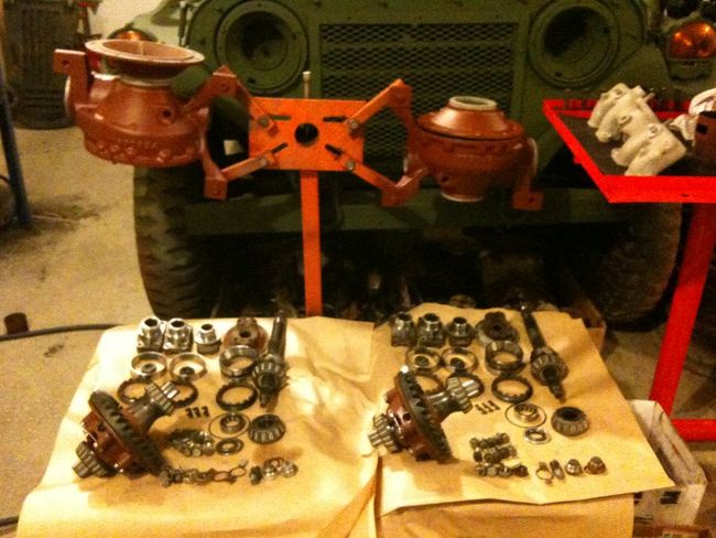
Cleaning and Conditions Check after Teardown:
I highly suggest you take everything and give it a good soak in a Parts Washer if possible. Also, if you choose to Sandblast your Diff Housings as I did, the Parts Washer is mandatory to ensure you flush out any sand or dust that may be hiding in the Pinion Oil Passages. Before you take the Chisel to the Yokes, check to see if they even have Wear Sleeves installed. On both of my Diffs, no Wear Sleeves were installed (still original Factory parts and seals). An easy way to check is to try to start a Wear Sleeve on a Yoke by hand. It will become obvious quite quickly.
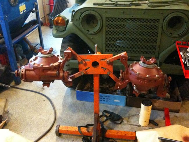
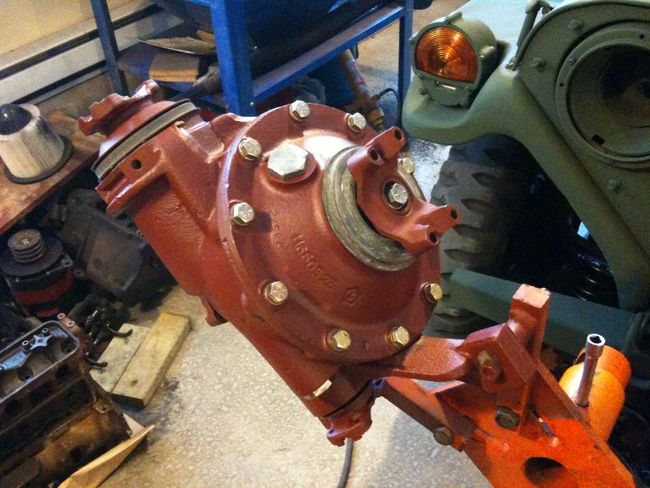
Heres a pic of mine back from a long soak in the Parts Washer. Everything looks much better now. I've also Primed the Housing and Cover. The final coat of Semi-Gloss Black will sprayed after all of the Gears and Seals are reinstalled.
Field Stripped 1100 Series minus Seals, Yokes and Bolts:
First things first, after everything is clean, you need to do a quick conditions check on all of the Bearings, Races and Gears. What we are looking for is extreme wear, pitting, corrosion damage etc. They will most likely be a bit dull where things are making contact, which in itself is fine. Pitting indicates that dirt or some other foreign objects were floating around in the oil. Really, no change from Wheel Bearings. If you wouldn't run it as a Wheel Bearing, you certainly don't want it inside a Diff. I'm not going to cover changing Bearings, but they have Timkin or SKF Part Numbers right on them, so in a bind, your local NAPA should be able to source them easily. It will require a Jaw Type Clamp Bearing Puller and an Arbour Press to replace them. If the Diff has sat for a while, it may have some corrosion on the Gears.
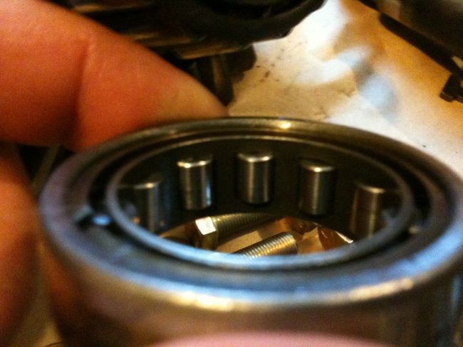
Carrier Bearing:
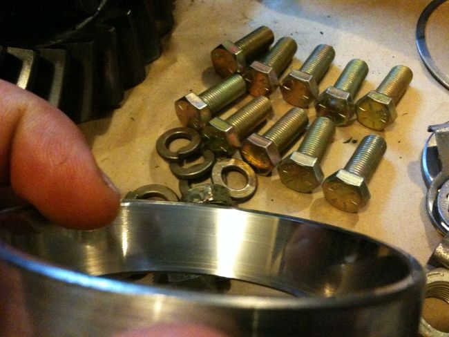
Carrier Bearing Race:
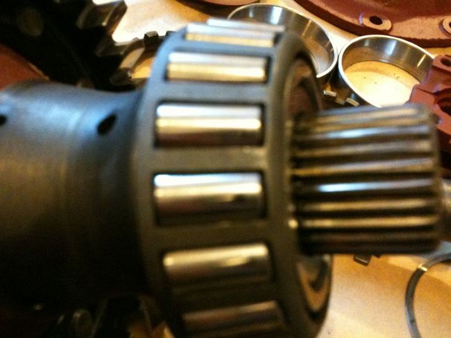
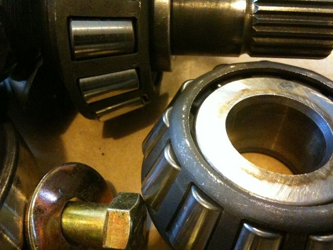
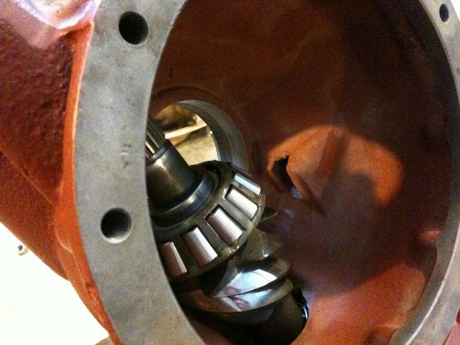
Front Pinion Bearings:
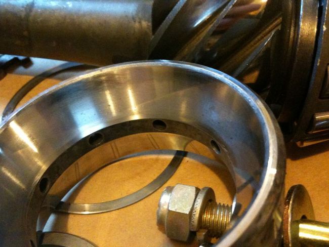
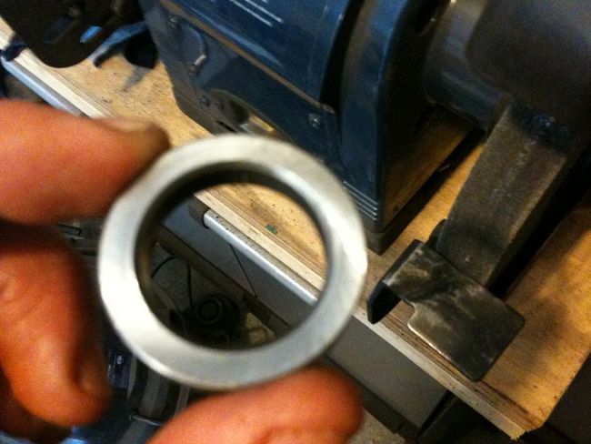
Front Pinion Bearing Race. This is an odd Race arrangement which allows for easy "Field Adjustments", and is probably only going to be found at an MV Dealer. On a normal Diff these are separate and pressed into the Diff Housing. This one is showing a little bit of wear, but definitely usable:
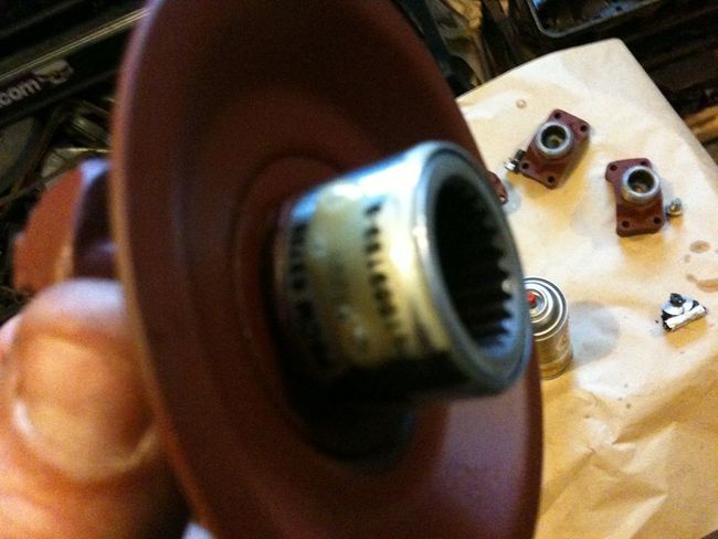
Rear Pinion Bearing. There is no Race for the Pinion Bearing, but rather the Pinion itself. Slide it on to the Pinion Shaft and check that its a snug fit with no slop. If the Pinion is pitted or gouged, kiss the Gearset Goodbye and get another Diff:
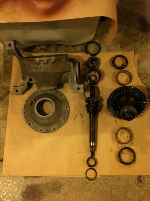
Pinion Gear:
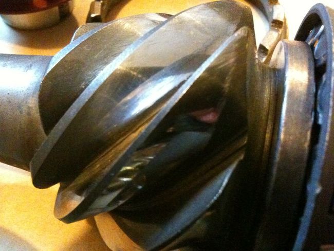
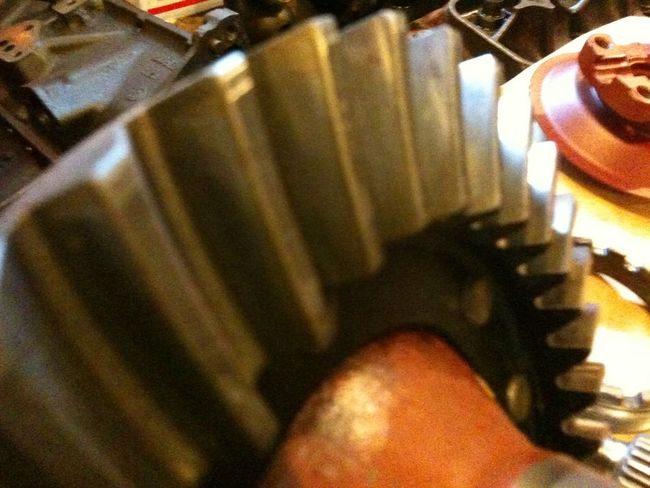
Ring/Crown Gear. Again, dull wear pattern is fine, pitting or any chipped teeth are not good:
So, these examples are what I would say constitute a Rebuildable Diff without changing Bearings, Races or Gears.
Checking and Setting Pinion Preload:
The First adjustment (most important one IMO) is the Pinion Bearing Preload.
This Diff uses the Strange Bearing Race arrangement that allows you to setup the Pinion Preload in a Bench Top Vice rather than inside the Housing which is really a huge time saver.
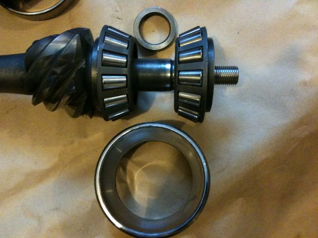
Basically, you have the Pinion Gear with the Inner Pinion Bearing pressed on it, and then the Spacer Shim, Races, and Outer Pinion Bearing which slip onto the Pinion. The little Spacer/Shim is what determines Pinion Preload. As you torque the Yoke on to the Pinion Gear, the Bearings will be pushed into the Races. The Shim allows the Pinion Nut to be torqued without crushing the Pinion Bearings. In order to increase Pinion Preload, the Shim needs to be thinner, to increase, thicker. In the case of our Diffs, I doubt anyone is going to encounter too much Preload. In order to increase Preload, you will either require thinner shims on hand, or the intestinal fortitude to sand down the existing shim. The issue with sanding down the shim is if you go too far, you will either again need another shim, or the super thin shims found in other Gear install kits to compensate. Honestly, if you take your time and make small adjustments, you won't have a problem:
Assemble the Pinion Gear, Spacer/Shim, Races, Outer Bearing and then install the Yoke with an old Pinion Nut. Use the old Nut as you'll be doing this many times and lightly Lube the Washer under the Pinion Nut:
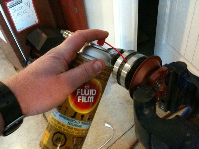
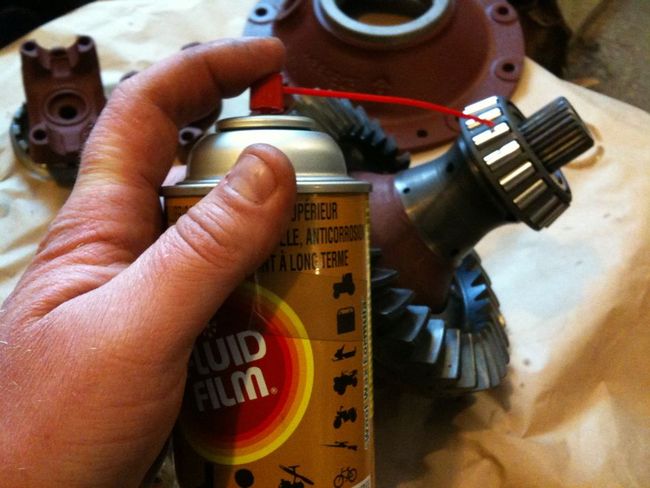
Lube up the Bearings. I like to use Fluid Film as it tends to stay where you spray it and its not sloppy. TM calls for Gear Oil, but frankly, I don't feel like handling Hypoid covered stuff. All you need here is some good lube to keep things rolling with minimal friction:
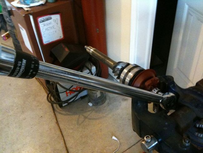
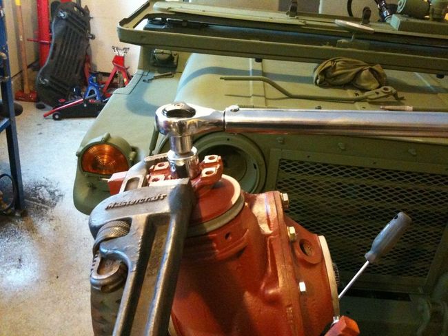
Torque Pinion Nut. I went with 70 ft/lbs. TM calls for 60 - 70. The key here is that whatever torque you use, must be the same for all other adjustments and final installation, as this will effect Preload. Be sure to spin the Race while torquing down the Pinion Nut to prevent anything from binding:
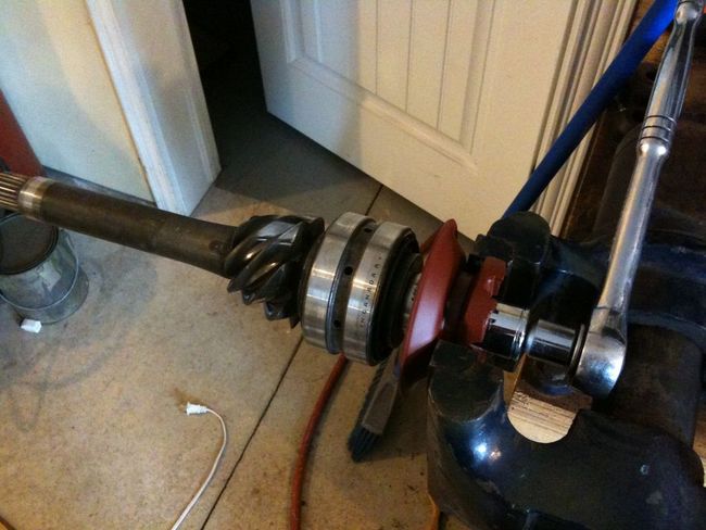
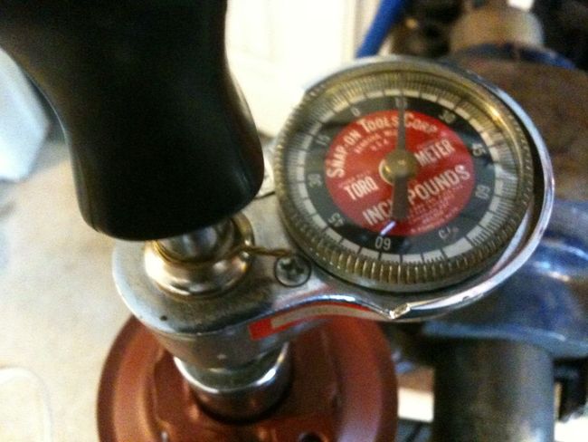
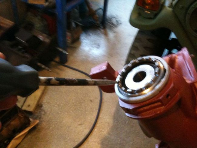
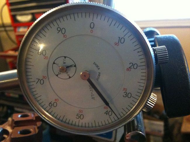
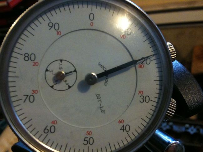
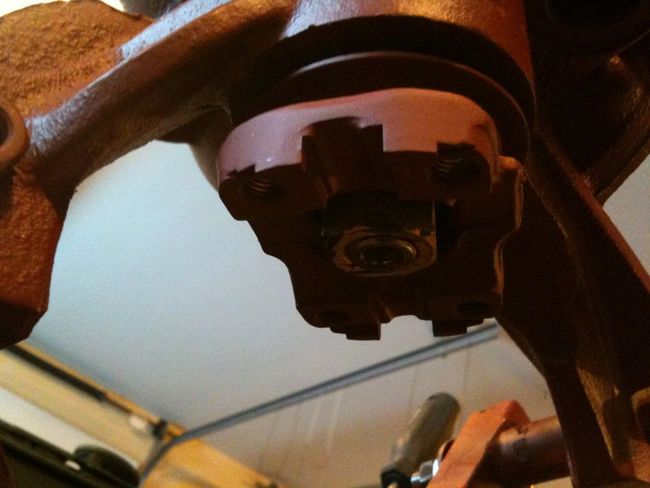
Now install the Pinion Assembly in a Vice clamped at the Race. Be VERY gentle here. You only need the Vice to lightly hold it in place. If its too tight you will distort the Race and wreck the Preload Readings. Now install the Inch Pounds Torque Wrench and give her a spin. In this case, it didn't even register on the Dial:
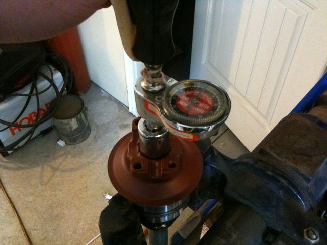
So, as you can see, there is Zero Pinion Preload on the Bearings in the current configuration. So, the Pinion Shim needs to be reduced in order to increase Preload.
Here is the intestinal fortitude bit. I'm not going to say this is the "Text Book" correct way to do things, but I chose to use the Tool Wheel on my Bench Grinder to Sand down the Pinion Preload Shim. Its tough to explain, but if you put your finger through the center of the Shim and gently press it against the Grinding Wheel, it will spin and be lightly ground at the same time. The result is a nice uniform grind. We are not trying to take much material off here, we're talking in the Thou's to 10 Thou's of an Inch. If it is too hot to hold, you've ground it too much. If you went ahead and bought a Shim Kit, this would be a case of trying the different Shims until you found what you need to achieve desired Preload:
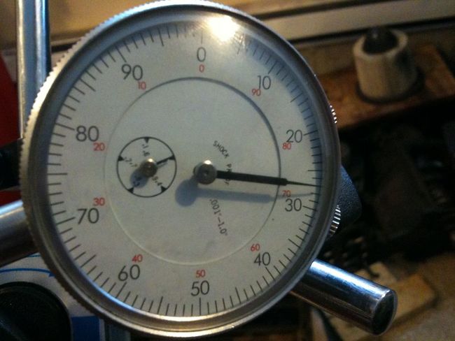
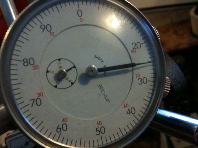
Re-assemble the Pinion Assembly in the same manner as before, and then re-check with the Inch Pounds Torque Wrench. Continue this process until you have achieved the Preload you want. I went with 15 Inch/lbs. It took me 3 full cycles to achieve it. Again, take your time here and only grind very small amounts. A thing to remember is you are looking for the Torsional Preload and not what it takes to get it staring to turn. In other words, the Needle will spike a bit when you go to start turning it. The actual Preload is what the Needle settles at on the Dial while its turning. This is where the Dial type Wrench is way better than a Click type wrench:
Thats all there is to it. Pinion Preload done!!!
Setting up the Diff:
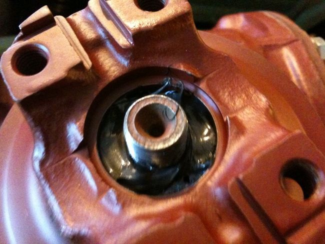
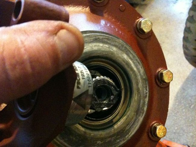
First install the Rear Pinion Bearing. I just used a really big Socket as a Bearing Driving Tool:
Then drop in the Bearing Spacer:
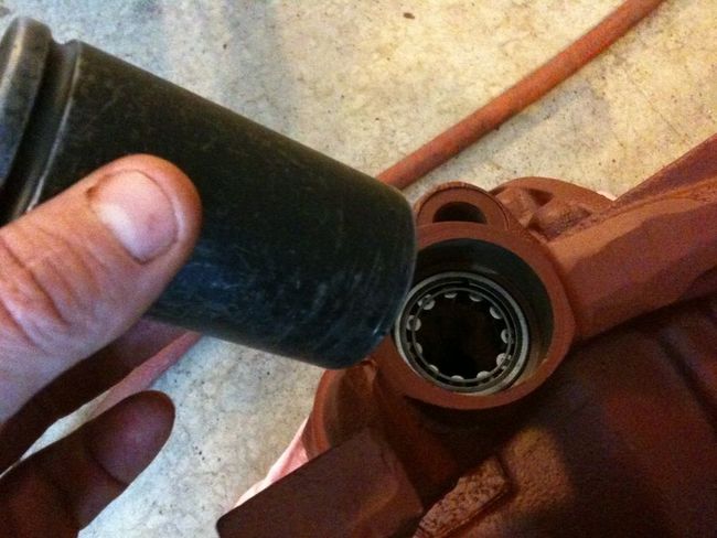
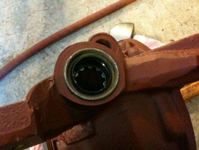
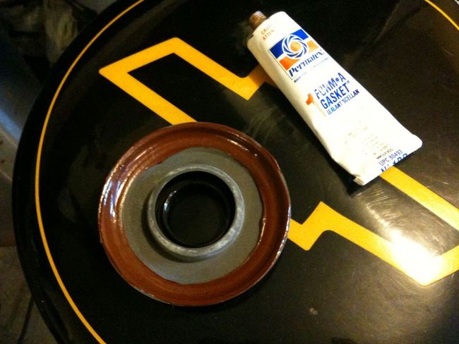
Now install the Small Seal. Spring goes towards the Diff. I put some Permatex around the inside circumferance of where the Seal sits rather than putting the finless brown trout on the Seal itself. Much cleaner and seals just as well. As well, clean up the Seal with some Brake Cleaner prior to install as it will probably be dusty and may have some cosmoline etc on it:
And finished with that end for now:
Not lets move on to the top end of the Pinion.
Take the disassembled Pinion Gear Assembly gently pass it through the front Pinion Opening and allow it to sit in the bottom:
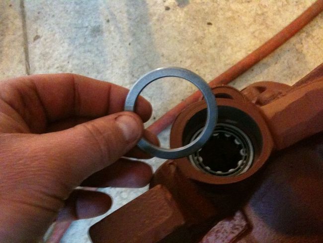
Then drop in the Pinion Depth Shim:
Next, the Pinion Race gets installed. I prefer to put this in dry/no lube on the outside or in the housing, as we don't want to encourage it to spin after assembly is done even though its a slip fit:
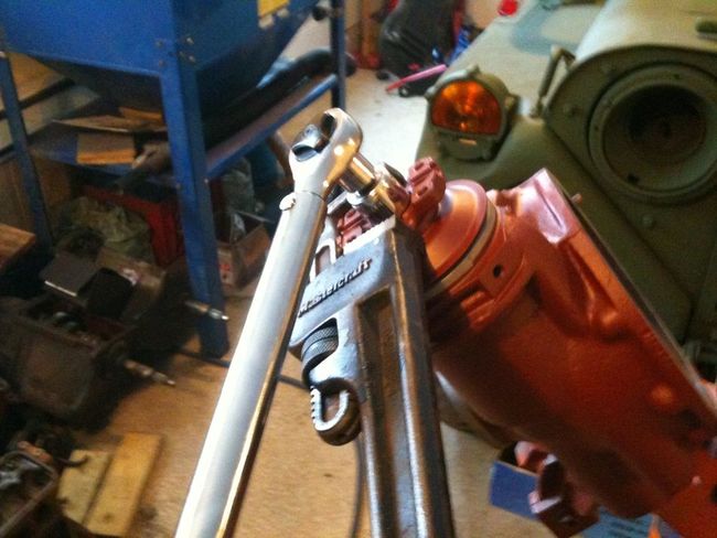
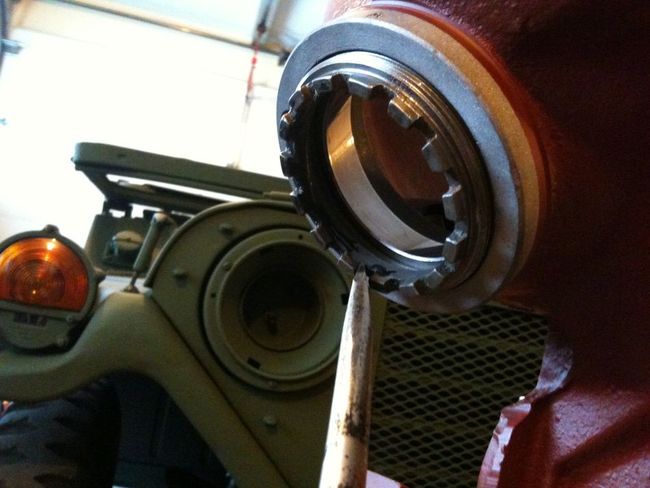
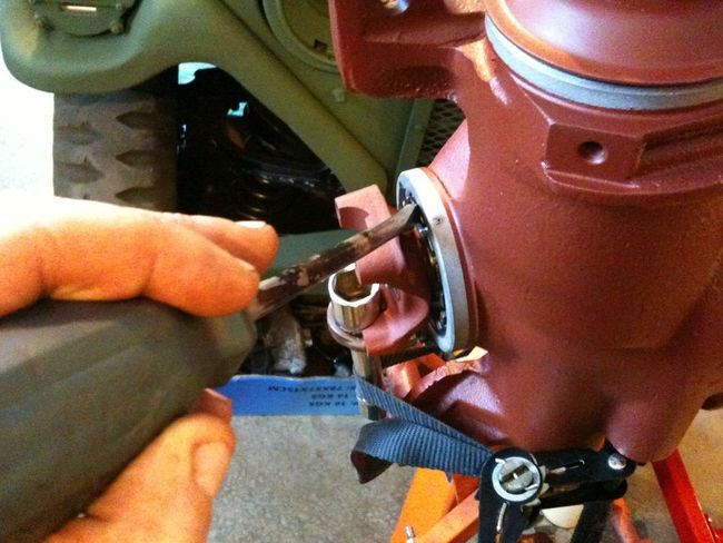
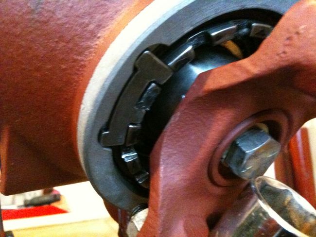
Drop in the Outer Pinion Bearing and then install the Adjustment Collar. For these Adjusters I just use a BF Flat Tip and a Hammer. If you want to spring for a Spanner by all means do so, but you can apply more than enough Torque with the above method. The TM lists something like 50 ft/lbs on the Adjuster Collar. Really, i'll continue to tap this thing until i'm approaching distorting the teeth, as the extra tightness won't harm anything or effect the Pinion Preload. What it will do is ensure that the Pinion Race doesn't spin in the Diff Housing:
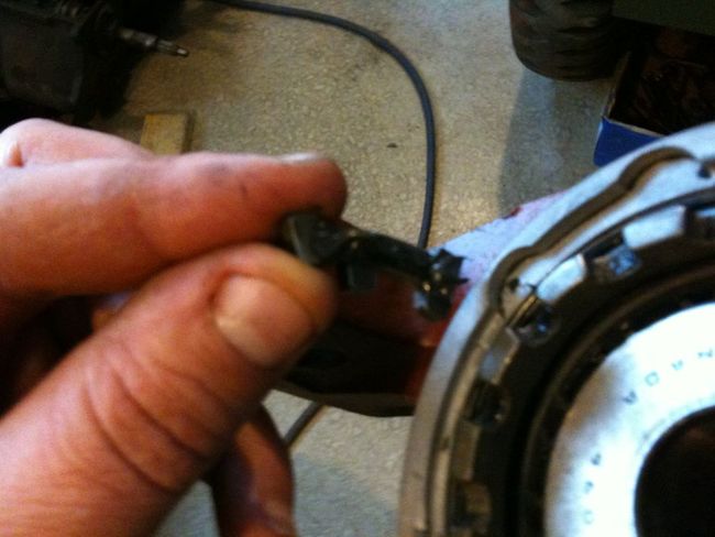
Lastly, install the Key Lock. Put a little dab of RTV on it to keep it in place. You may have to increase or decrease the Adjuster in order to get the Key in. Default should be tightening, but again, do what is required. Once its in, I like to give the Adjuster an extra tap to lock the Key in place:
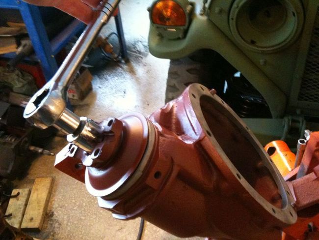
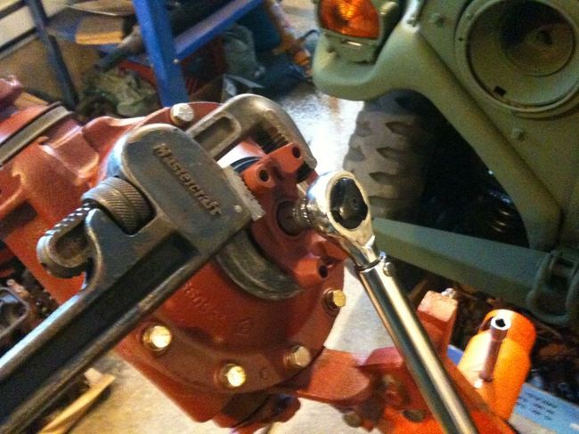
Now you can pop the Pinion back up and install the Yoke. Remember to use the same Torque specs you used to set the Preload while continuing to use the old Nut, and spin the Pinion every so often to keep things from binding. Also, don't install the Seal yet. You want to keep any extra friction to a minimum until after the Backlash is set:
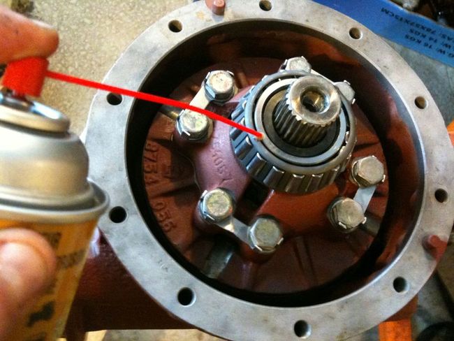
Once thats done, give the Pinion a few turns in the Diff Housing and spray a bit more lube up into the Bearings from inside the Housing:
Thats it, Pinion installed ready for setup...
OK, lets get on with the Carrier install.
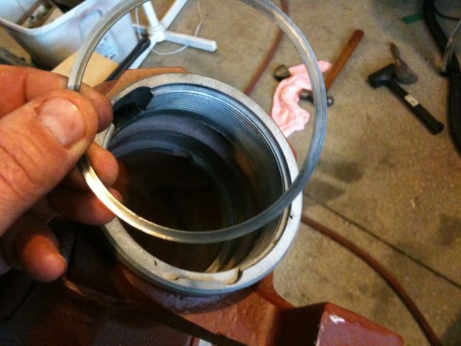
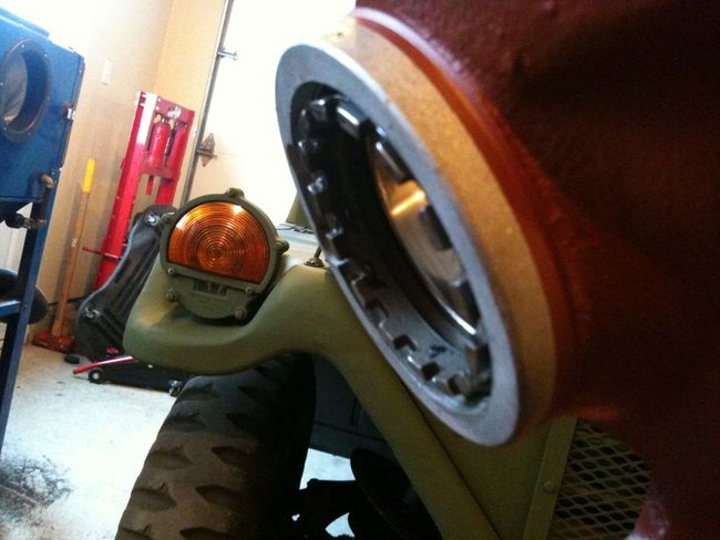
First, install the Carrier Bearing Race and Adjuster into the Diff Housing portion. You may need to tap the Race in. Again, I like to install it dry for the same reason as the Pinion Race. Put a little lube around the threads on the Adjuster. You should be able to turn it by hand until you come up against the Race, then you may need to lightly tap it with the BF Flat Tip:
Continue installing until the Adjuster is roughly flush with edge of the Housing:
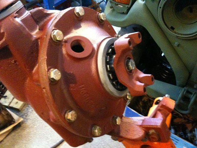
Next, lube up the Outer Carrier Bearing:
Gently set Carrier into the Housing and then Lube up the other Carrier Bearing:
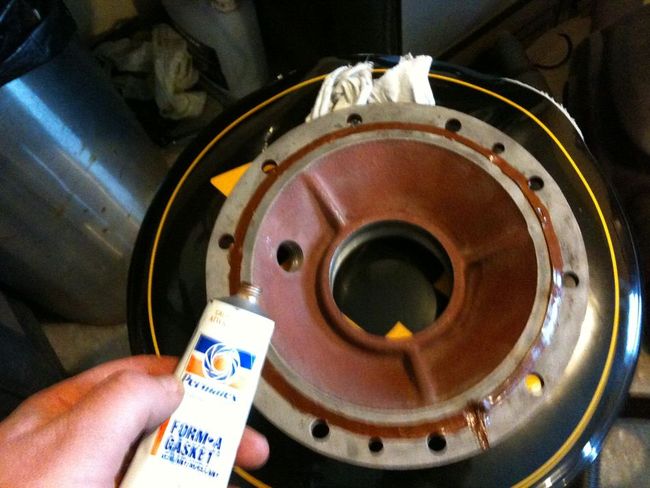
Next we will prepare the Diff Cover. In my case, i'm just using RTV, and since I don't plan on running a Pattern because we are not making any drastic changes to the Gear Set alignment, so the Diff Cover will be sealed up for good. Don't go crazy with the RTV. A little bead is plenty. If you are using a Paper Gasket, it needs to be installed regardless as it is thick enough to potentially effect the Backlash setting:
Install and Torque the Cover Bolts, IIRC, I went with 45 ft/lbs:
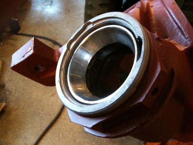
Then install the Outer Carrier Bearing Race and Adjuster Nut in the same manner as the other side. Continue to tighten it until there is no side to side slop in the Carrier:
Pop the Yokes on, again leaving off the Seal. I tightened mine to 50 ft/lbs:
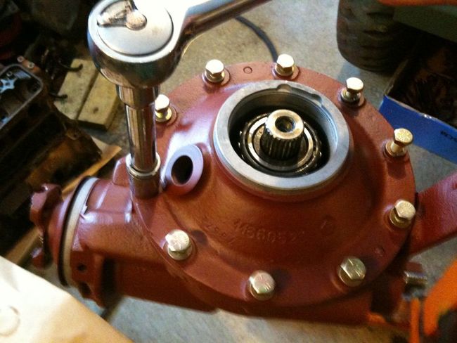
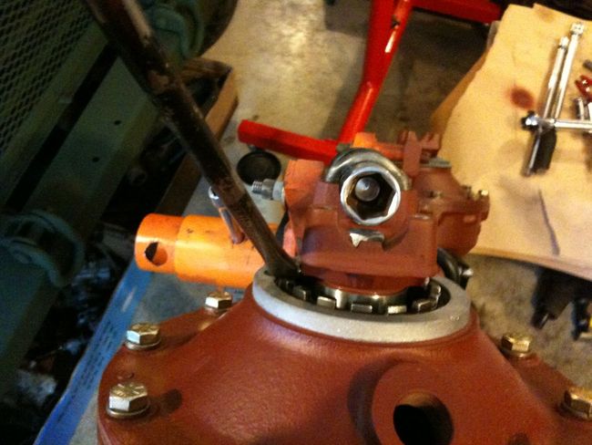
Now this next step may seem strange, but it will make sense in a minute. Install a 3/4" Socket with an extension attached in place of where the U-Joint will sit. Same thing for the other side. A 19mm will work there (now you have a use for that metric socket):
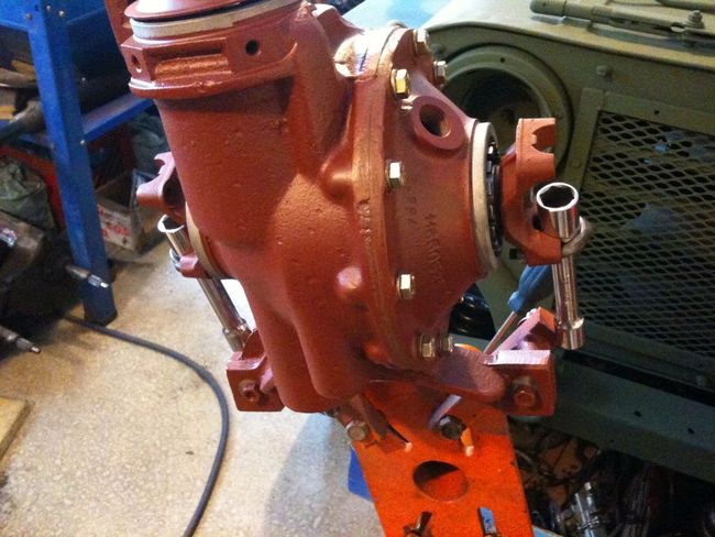
Lastly, from the Diff Cover side, take up all of the slack in left in the Adjuster Nut, ie pound it in nice and tight:
Now we are ready to start setting Backlash...
Setting Backlash:
Before we start fiddling with the Backlash, remove the Socket Extensions and give the Guts (Pinion and Carrier) a few spins in the Housing to get seated. Get in to the habit of spinning things every so often.
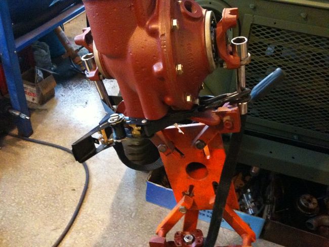
Now the fun stuff. Wrap a strap or something similar around the Socket Extensions and cinch it down. What we want to do here is keep the Carrier Yokes from turning while we establish the Backlash:
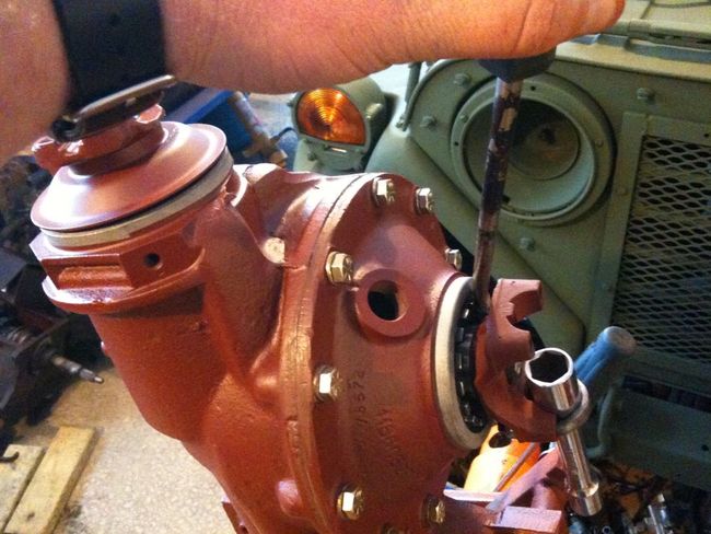
Install a Driveshaft Bolt into the Front Pinion Yoke and turn the Pinion clockwise until all of the slack is out of the Gearset. We are talking a 10th of a turn, you'll feel it.Now setup your Magnetic Base Dial Indicator. This is time consuming setting it up. Like the old adage, "Garbage in = Garbage out". If you don't take the time line everything up perfectly, your numbers are going to be cocked. Setup of Dial Indicator is detailed in TM 34P. You want the Dial Indicator Plunger directly in line with the Bolt and slowly touch it down on the bolt and then back it off slightly to Zero:
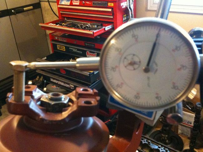
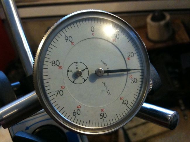
Take your first Backlash Check by rotating the Pinion towards the Dial Indicator until the slack is taken up between the Pinion and Ring Gears. My first crack at it was .038". Not bad for a start. If you are installing a new Gearset or a complete set of new Bearings, this is the time to run a Gear Contact Pattern with the Gear Marking Compound. The TM 34 covers how to run a Pattern:
Since we are aiming for Backlash in the mid .020s, we need to tighten up the Backlash a bit. In order to do that, the Ring Gear needs to be moved closer to the Pinion Gear. Remove the Dial Indicator. Then start by loosening the Housing Side Adjuster Nut by a few blows with the Hammer and BF Flat Tip:
Then move over to the Cover Side Adjuster and take up all of the slack again. If you are making dramatic adjustments, you are going to need to remove the strap and spin the guts a few times:
Once your done, reinstall everything and lets check the Backlash again. Down to .027" now. Getting closer and well within the zone of .022" - .036". I'm going for even a little more snugness:
So, using the same steps before, move the Ring Gear closer to the Pinion by loosening the Housing Adjuster and Tightening the Cover Adjuster. Then check Backlash again. .019". A tad too tight according to the TM:
So we are going to need to move the Ring Gear away from the Pinion slightly. So, in reverse order and approx half the distance from the last adjustment, tap in the Adjuster Nuts, then check Backlash again. Bingo, .025":
Now its time to cinch everything up. Because we are happy with the Backlash, its time to tighten everything down. What I am basically doing is giving both Adjuster Nuts a couple of confirmatory taps, starting with the Cover Side, and then the Housing Side. As tight as you can hammer them down is good here. Once everything is fully seated install the Lock Keys in the same manner as the Pinion Adjuster Nut:
Once this is done, give everything a good couple of spins and taps, and do a final check of the Backlash. In my case it landed at .026". Not too bad at all:
Installing new Seals
Start by removing all of the Yokes.
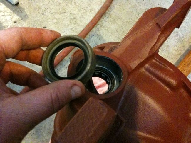
Then we will install the Front Pinion Yoke Seal. Clean it up first then lay a bead of RTV around the inside edge:
Then go ahead and tap it on to the Housing:
Lubricate the Pinion Yoke Wear Sleeve with some lube (Fluid Film in my case):
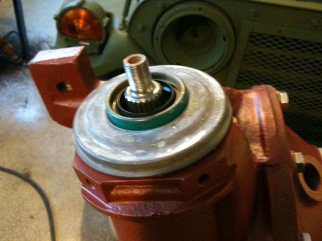
Install Yoke, and then fill in the void between the Yoke and the Pinion Shaft with RTV. This will keep oil from seeping out the Splines:
Then Torque it down to the correct amount (70 ft/lbs):
Same same with the Rear Pinion Yoke only with 50 ft/lbs Torque:
Same drill with the Side Gear Seals, only this time, put some RTV on the end of the Output Shaft:
Torque the Yoke down to 50 ft/lbs, and then repeat for the other side:
Lastly, install Drain/Check Plugs and Breather:
Now, most importantly, treat yourself to a pat on the back with a dram of your favourite Scotch:

Take Dram of Scotch, spark up a good smoke, and appreciate your hard work: